Target Mean Analysis
This analysis creates a plot featuring response curves. Another similar analysis is available in BayesiaLab, which produces a tabular report with unit effects and related statistics. Please see Total Effects on Target.
Context
- This analysis visualizes the relationships of selected Driver Nodes in a network with the Target Node in the form of curves.
- This analysis is often used as a reference point in key driver analysis (see Chapter 8).
Example
- The following example is taken from Chapter 8: Probabilistic Structural Equation Models for Key Driver Analysis.
- The network below features the Target Node at the center of the network for which we want to analyze its response to changes in the Driver Nodes connected to it.
- The node is the Target Node.
- The nodes , , , and are the Driver Nodes under investigation.
- In traditional statistics, the Target Node would be the dependent variable, and the Driver Nodes would be considered independent variables.
While the term “driver” suggests a causal relationship between a Driver Node and the Target Node, we are only examining associations, which may or may not be causal. So, the direction of the arcs in this network does not imply a causal direction. For a formal treatment of causality, please see Chapter 10 — Causal Effect Estimation.
Usage
- Make sure you have defined a Target Node.
- In Validation Mode
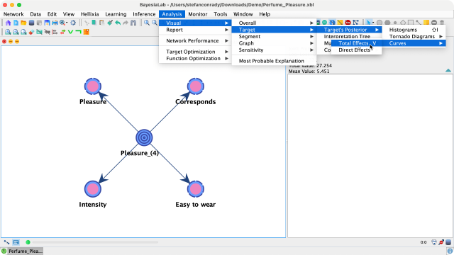
F5, select the nodes of interest, i.e., the Driver Nodes, and go toMain Menu > Analysis > Visual > Target > Target's Posterior > Curves > Total Effects. - If you have not selected any node, BayesiaLab will use all connected and observable nodes for the analysis.

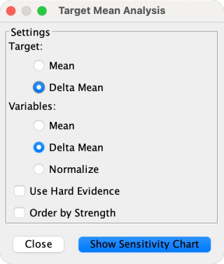
- A window comes up, which allows you to set several options for the chart to be displayed.

-
Given that our Driver Nodes were not all recorded on the same scale, we check the
Delta Meanboxes for bothVariablesandTargetfor ease of interpretation. -
Clicking the
Show Sensitivity Chartbutton brings up the plot. -
In this chart, we see two simulations:
- The x-values of each Driver Node are simulated across their variation domain using Minimum Cross-Entropy (see Chapter 7, Numerical Evidence — MinXEnt).
- These x-values are used as inputs for inferring — with the network — the y-values of the Target Node.
-
The x-y value pairs of Driver Nodes and the Target Node produce a set of response curves, i.e., the Total Effects Curves.
-
They are shown simultaneously and can be distinguished by their randomly assigned colors.
Calculating Means
- In our example, all Driver Nodes are discrete with integer values. As a result, calculating the mean value of the Driver Nodes’ states is straightforward.
- In alternative cases, BayesiaLab will compute mean values as follows:
- If a node is categorical, but has numerical values associated with its categorical states, the mean is computed from the associated values.
- If a node is continuous, its mean value is computed from the states’ intervals.
- If none of the above applies, BayesiaLab uses a set of default values enumerating the states beginning with 0 for the first state.
Please note that the plotted response curves do not have any underlying equations. There are no functions and parameters that were estimated. The curves are purely the result of inference performed with the given network.
Interpretation
- This visual analysis shows how changes in the mean values of the selected Driver Nodes in a network are associated with changes in the mean value of the Target Node.
- To provide some intuition for the mean value simulations of the x-values and the inferred y-values, the following panels compare the marginal distributions of all nodes with their posterior distributions after simulating a one-unit increase (using MinXEnt) for .
Marginal Distributions | Posterior Distributions |
|---|---|
Loading SVG... | Loading SVG... |
- Compare the marginal distributions of the Target Node and the Driver Nodes (on the left) with the posterior distributions of the same nodes on the right.
- Here, the +1 increase in is associated with a 0.78 increase in the mean value of the Target Node .
Workflow Illustration
Context
- This report calculates the Total Effect of each selected node (or all nodes) in the network on the Target Node.
- Generating this report is often used as a reference point in a key driver analysis see Chapter 8.
Total Effect Definition
-
The Total Effect of a node on a Target Node is the derivative of the Total Effects Curve, computed at the a priori mean of that node, i.e., Delta Mean=0.
where is the node of interest and is the Target Node.
-
The Total Effect represents the impact of a small change of the “mean” of a node on the “mean” of a Target Node.
-
The Total Effect is the ratio of these two values.
Total Effect Curve
-
The Total Effect Curve is plotted using BayesiaLab’s Target Mean Value Analysis function.
-
For illustration purposes, we borrow a plot produced by another BayesiaLab function, the Target Mean Analysis.
- Delta Mean=0 is marked with a black dashed vertical line; the derivative of is highlighted with a cyan-colored dashed tangent.

