Using the Graph Panel
Context
- In BayesiaLab, the Graph Panel provides an interface for modeling, viewing, and analyzing Bayesian networks.
- A network consists of variables represented by nodes and relationships between them, which are represented by arcs.
- While the Modeling Mode
F4is active, you can add, modify, or remove these elements in the Graph Panel. - You can also create, view, and modify the probability distributions of nodes.
Toolbar
- From the Toolbar, you can activate specific editing modes for modifying all aspects of a network graph inside the Graph Panel.
- The full range of editing modes in the Toolbar is only available when you are in the Modeling Mode
F4.
Selection Mode
The Selection Mode is active by default.
- Click on a node or an arc to select the object at the cursor position.
- Click again to unselect the object.
- Draw a box around a group of nodes and/or arcs to select them.
- Click while pressing
Ctrlto add to an existing selection of objects. - A selected node is highlighted with orange corners.
- A selected arc is marked with an increased arc thickness.
- Click and hold the selected objects to move them within the Graph Panel.
Node Creation Mode
In this mode, you can add new nodes to the Graph Panel.
- Click on the icon in the Toolbar to activate the Node Creation Mode.
- While the Node Creation Mode is active, the cursor appears as a pointer.
- Click on the Graph Panel to place the new node.
- By default, the first new node is named , with subsequent new nodes being named , , etc.
- Whenever a new node is created, BayesiaLab generates a “minimal” probability table with the binary states and .
- The Node Editor indicates that no probabilities are assigned to the states.
- Without any probabilities defined, the new node is marked with a warning sign.
- You can also access this mode using the shortcut
N, soN+ click on the Graph Panel places a new node at the position where you click.
Function Node Creation Mode
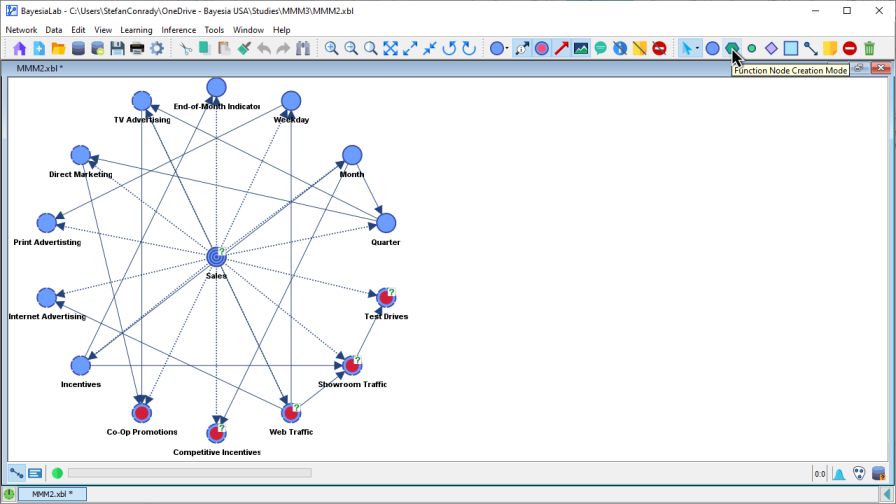
This mode creates Function Nodes.
- Click on the icon in the Toolbar to activate the Function Node Creation Mode.
- While the Function Node Creation Mode is active, the cursor appears as a pointer.
- Click on the Graph Panel to place the Function Node.
- Following the same pattern as the Node Creation Mode, the default names of new Function Nodes are , , etc.
- The warning triangle indicates that the
Formulatab in the Function Node Editor is empty. - The shortcut for accessing this mode is
F.
Constraint Node Creation Mode
- Click on the icon in the Toolbar to activate the Constraint Node Creation Mode.
- Click on the Graph Panel to create and position the new Constraint Node.
- The naming convention is the same as above, i.e., , , , etc.
- The shortcut for accessing this mode is
K.
Utility Node Creation Mode
- Click on the icon in the Toolbar to activate the Utility Node Creation Mode.
- Click on the Graph Panel to create and position the new Utility Node.
- The naming convention is the same as above, i.e., , , , etc.
- The shortcut for accessing this mode is
U.
Decision Node Creation Mode
- Click on the icon in the Toolbar to activate the Decision Node Creation Mode.
- Click on the Graph Panel to create and position the new Decision Node.
- The naming convention is the same as above, i.e., , , , etc.
- The shortcut for accessing this mode is
A.
Arc Creation Mode
The Arc Creation Mode allows you to draw arcs between nodes.
- Click on the icon in the Toolbar to activate the Arc Creation Mode.
- Once activated, the cursor turns into a crosshair.
- Click and hold the mouse button on the node where you want the arc to start.
- While holding the mouse button, drag the cursor to the destination node, then release the mouse button.
- The shortcut for the Arc Creation Mode is
L(as in Link).
Note Creation Mode
The Note Creation Mode allows you to add comments as additional elements to the Graph Panel. Typically, you would add explanatory annotations to a network.
- Click on the Note Creation Mode icon in the Toolbar.
- The appearance of a Note can be styled in the Note Editor.
- All notes will be saved with the network file.
Node Exclusion Mode
The Node Exclusion Mode allows you to exclude nodes temporarily from actions that otherwise apply to all nodes in the network graph. For instance, you can temporarily prevent nodes from being included in network learning, without having to delete them permanently (see Deletion Mode).
- Click the
Node Exclusion Modeicon . - Click on the nodes to exclude.
- Once excluded, nodes are marked with the “wrong way” symbol .
- You can exclude multiple nodes by drawing a box around them.
- Holding
Xkeeps you in Node Exclusion Mode, and you can quickly exclude all the nodes on which you click. - Clicking again on any excluded nodes returns them to their normal state.
Deletion Mode
In the Deletion Mode, you can permanently remove nodes and arcs from the network graph.
- Click on the Deletion Mode icon in the Toolbar.
- The cursor changes into a red X.
- Click on the nodes or arcs you wish to delete.
- You can also draw boxes around the nodes or arcs to be deleted.
- Any underlying data will be deleted along with the node.
- All connected arcs will be deleted with the node.
- As an alternative to activating the Deletion Mode, you can select nodes and arcs and then press the
Deletekey. - Finally, you can delete nodes and arcs by right-clicking on them and then selecting
Deletefrom the Context Menu.
While excluding a node sets it aside temporarily until you need it again, deleting a node removes it permanently from the network.